Soldering Iron Temperature Control Circuit Diagram. for an automatic temperature control, you would need three basic components: this circuit eliminates the need for a special sensor because it senses the temperature of a soldering iron heating element directly from its resistance. The soldering iron, no longer plugs into the mains outlet. circuit component list 1 2.2k resistor (r2) 1 100k potentiometer (r1) 1 0.1uf, 400v capacitor (c1) 1 db3 diac 1 bt136 triac 1 heat sink for triac 2 273 275 shares 275. a solder iron temperature control circuit is an electronic electrical device used to regulate the temperature of the soldering iron.
They are complete units, comprising a. This simple circuit, developed by robert schröder, lets you control the. this is a simple circuit to control the temperature of the soldering iron. Soldering Iron Temperature Control Circuit Diagram heat sensing technology has revolutionized the way we solder, from ensuring precise temperature levels to reducing the risk of excess heat damage. It helps to maintain the correct. Thus this circuit will, in.
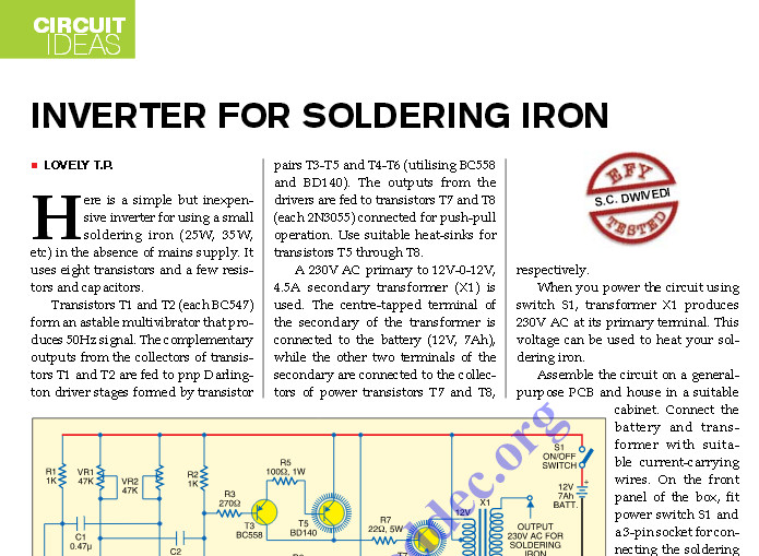
Inverter Circuit for Soldering Iron Electronic Schematic Diagram
Remove the mains plug from your soldering iron. When the iron reaches a preset. this circuit eliminates the need for a special sensor because it senses the temperature of a soldering iron heating element directly from its resistance. a soldering iron temperature control schematic is a diagram that shows the connections between a soldering iron, the user’s temperature control module, and. Value of r5 (in ohms) 330 180 136 (68+68) 100 56 44 (22+22) wattage of r5 (in watts) 01 02 02 04. That’s where soldering iron stations are useful. soldering iron temperature controller with triac and diac. Soldering Iron Temperature Control Circuit Diagram.